In terms of building materials, industrial products, daily necessities, floor leather, floor tiles, artificial leather, pipes, wires and cables, packaging films, bottles, foaming materials, sealing materials, and fibers, PVC was the world`s largest production of general-purpose plastics, and its applications are very widely. Widely used in all aspects
PVC is a white powder with an amorphous structure. The degree of branching is relatively small. The relative density is about 1.4. The glass transition temperature is 77~90°C. It begins to decompose at about 170°C. It has poor stability to light and heat. After prolonged exposure to sunlight, it will decompose to produce hydrogen chloride, and further automatically catalyze the decomposition, causing discoloration, and the physical and mechanical properties also rapidly decline. In actual applications, stabilizers must be added to improve the stability of heat and light.
The production process of PVC Resin SG8 and PVC RESIN SG5 is basically the same, and the production equipment is exactly the same. The main difference lies in the formulation of additives, polymerization temperature, reaction pressure and so on. The reaction temperature and reaction pressure of SG-8 resin have basically reached the working pressure limit of the polymerizer. The reaction requirements are relatively strict, and the requirements on operation, safety, technology, and personnel quality are more stringent, and the resin quality is more difficult to control.
PVC RESIN SG8,Pvc Resin Sg8,Pvc Resin K58,Suspension Pvc Resin Henan Shunbang Chemical Industry CO.,Ltd , https://www.sbpolymer.com
This is the interception of a certain day's condensate flow and level history of the operating curve; blue for the flow curve, black for the liquid level curve; visible, flow and liquid level fluctuations are large, generally craftsman manual operation, liquid Bits are not self-adjusting, and the labor intensity is high; especially: the flow rate varies from a few to hundreds of parties, the flow rate and liquid level fluctuate greatly, and the recording curve is like the Great Wall, which can be seen if this system is used in this way. The control method is very difficult for the system's on-site operation, data recording, etc. For this, we must find a suitable control method to solve the current process.
Second, the implementation of cascaded homogeneous control system due to the uncertainty of the liquid level changes, if you want to completely balance the liquid level and flow, it is almost impossible, if you use a single channel control often overlooked, can not solve the fundamental problem, This specifically introduces cascaded uniform control. The following analysis of the process of the system:
1, process conditions:
The stability of the liquid level in the light ash section washing condensation tower is achieved by controlling the discharge amount at the bottom of the tower; therefore, its discharge amount must be unstable. The discharge volume of the washing and condensing tower is just the feeding amount of the thin liquid tower in the steaming section; therefore, when the liquid level in the front tower is stabilized, the amount of feed in the rear tower cannot be stabilized. On the contrary, if the stability of the feed amount of the rear tower is ensured, the liquid level of the front tower is bound to be unstable. This means that there is a contradiction between the requirements for the stability of the front tower level and the amount of feed in the rear tower, and it cannot be guaranteed at the same time.
2, instrument control program exploration:
(1) One way to solve this contradiction is to add a buffer tank with a certain capacity between the front tower and the rear tower. But this requires the addition of a set of container equipment, resulting in increased investment, increased floor space, and increased energy consumption for liquid delivery. Especially serious is the condensate residence time is long, will crystallize in the pipeline and the buffer tank, has become the material to cut off and so on the undesirable result, obviously considers the overall system quality cannot use this method!
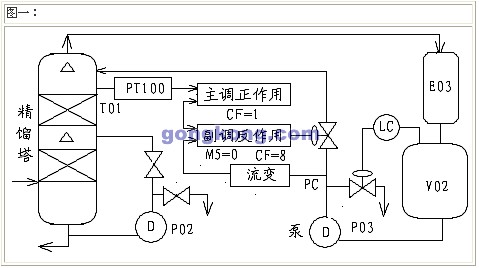
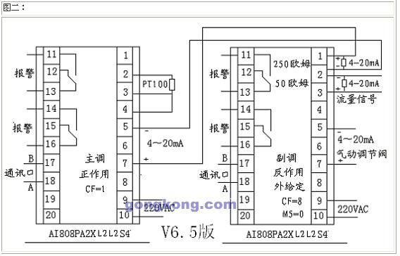
(2) The second method to solve this contradiction is to implement a cascaded uniform control system. The output of the liquid level controller is to be used as a given value of the flow controller. The flow control output is used to operate the actuator. Since a secondary circuit is added in this system, it can be overcome in time due to pressure changes in the tower or at the discharge end. The flow changes. In this way, a homogeneous control system featuring the cascade control system is formed. This system uses the AI-808A2X3L2L2S4 instrument from Xiamen Yudian Automation Technology Co., Ltd. to form a cascade-level uniform control system.
3, Cascade Uniform Control System Principle:
Cascade uniform control is the use of cascade control structure, the core of the ratio control, the introduction of flow signal at the same time to control the liquid level to form a uniform control, the control flow chart is as follows: 
4. Determination of the positive and negative effects of the main control and deputy control instruments of the cascade-level uniform control system The main and secondary control instruments used in this system are AI-808AX3L2L2S4; the positive and negative effects of the control instrument are determined in the entire control system. It is also very important; for the master AI-808A instrument, the rise and fall of the liquid level will directly affect the increase and decrease of the flow, that is, when the liquid level rises, the controlled flow needs to increase, and when the liquid level decreases, the flow Need to reduce, so the main control instrument should be positive action control, setting the instrument when the CF=1 instrument will be positive action control. For the secondary control instrument, when the output of the master control increases, the setpoint SV of the secondary control increases, and in order to increase the flow rate, the output of the meter must also increase. Therefore, the instrument uses the reactive adjustment, and the CF parameter is set to 0.
5. The debugging process of string-level uniform control is introduced in many books. In the debugging of cascade-level uniform control, the main control and deputy control are firstly debugged under the manual state, and then the main-subsidiary debugging is performed one by one. Although the method can get satisfactory results, but it takes more time to debug; according to my experience in on-site debugging, you can only manually control the deputy control in the entire process, which also facilitates the control parameters of the master control instrument. The reason why the cascade uniform control system can coordinate the relationship between the two variables is achieved through the tuning of the control parameters. In the cascade uniform control, the parameter setting is not to make the variable return to the given value as soon as possible. Instead, the variables are required to change slowly within the allowable range, and the parameters tested are also different from the general system. The general system is to change the parameters from the big to the minor, the cascade uniform control system is just the opposite, there is a small to large key. Moreover, special attention should be paid to the fact that in the cascade-level uniform control system, the controller generally adopts pure proportional control. As long as the requirement is relatively high, proper integral action is introduced to prevent the deviation value from exceeding the allowable range. After the deputy control instrument is hit manually, the output flow can be controlled according to the measured value of the main control instrument, the relationship between the main control fluid level and the secondary control flow, the relationship between the flow rate change and the sub-control manual output can be set to set the master control. And the value of the deputy control instrument.
6. Parameter setting of the AI-808AX3L2L2S4 master control instrument parameter setting: HIAL=600LOAL=200CtrL=4M5=0P=8T=0CTL=4Sn=33DIP=1dIL=0dIH=800CF=1addr=1bAUd=9600
Deputy control instrument parameter setting: HIAL=700LOAL=100CtrL=4M5=0P=4T=0CTL=2Sn=32DIP=1dIL=0dIH=900CF=8addr=2bAUd=9600
The above parameters are obtained through the simulation site, after the actual use of the site observation, fine-tuning the results. After light-duty and steam-sucking technicians tried for a period of time, the results were good, as shown in Figure 3 (after cascade-level uniform control):
Figure 3: (Cascade evenly)
This is the interception of a certain day's condensate flow and level history operation curve; blue for the flow curve, black for the liquid level curve; visible, flow and level fluctuations are flat, very smooth, light gray and steam suction two sections Material process is smooth! In particular, the light gray craftsman has applied a double uniform adjustment system to reasonably control the balance of condensate materials, save energy, lay a foundation for the high yield of soda ash, and reduce the labor intensity!
III. Concluding remarks After the whole system was introduced with cascade-level uniform control, the stability of the system was greatly improved, which effectively solved the unnecessary losses caused by excessive system fluctuations and saved human resources.
Application of Xiamen Yudian AI Artificial Intelligence Industrial Regulator in Cascade Uniform Control System
I. INTRODUCTION In the chemical industry, various production equipments are closely linked. Often, the discharge of the previous equipment is the feeding of the latter equipment; the equipments are interrelated and influence each other. For example, in the light-grey section, the condensate from the condensation tower is pumped into the trough of the desiccant tower in the distillation section. In this process flow, the material balance between the two sections is related, and the light ash section is used to wash the condensation tower. The production process is carried out steadily, that is, to ensure that the bottom of the condensing tower is relatively stable (previously a liquid level control system was set up); at the same time, it is hoped that the feeding amount of the dilute liquid tower in the distilling section can be kept relatively stable. It is possible to consider, but there will be contradictions in the tower systems that have material links before and after. See Figure 1 (traffic and liquid level control curves individually):
Figure 1 (single channel control)
Figure 2: Block Diagram of Uniform Control System
