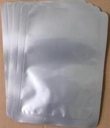
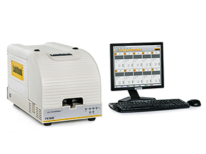
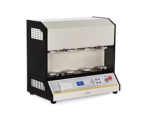
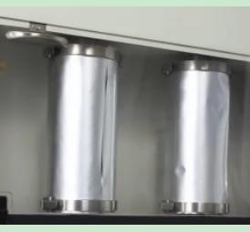
Abstract : Duck neck is a common flavor snack, delicious and tasty, which is popular with consumers. During the circulation process of the duck neck finished product packaging, quality problems such as bagging and air leakage often occur, which brings unpleasant consumer experience to consumers. The problem of causing similar quality problems in the duck neck is often caused by poor barrier properties of the packaging material. This article uses the OX2/230 Oxygen Transmission Rate Test System and FDT-02 Kneading Tester independently developed by Jinan Languang Electromechanical Technology Co., Ltd. to verify the barrier properties of the duck neck aluminum-plastic composite packaging bag and explains the principle of the device. The parameters and operation process have certain reference and guiding significance for controlling the barrier properties of aluminum-plastic composite film. Keywords : duck neck, meat products, oxygen permeability, oxygen barrier, aluminum-plastic composite film, aluminum composite film, kneading, pinhole 1 , the meaning Duck neck is a high-protein, low-fat food, with Qi and tonic, beauty and other beauty effects, fresh and beautiful, is a leisure food for all ages. The rich nutrients of duck neck also impose stringent requirements on the barrier properties of packaging materials. If the oxygen barrier properties of the packaging materials are low and the oxygen transmission rate is high, the amount of oxygen that the neck of the duck is exposed to is higher. Prone to mildew, swelling bag, odor and other quality problems. At present, most of the common duck necks are packaged in aluminum-plastic composite film. For such aluminum foil-containing packaging materials, due to the presence of aluminum foil material, it has the characteristics of impatience in rubbing, that is, it is susceptible to creases under the influence of external forces. Pinholes and other defects, resulting in reduced barrier properties, so for aluminum-plastic composite film, aluminized film plastic composite film materials, oxygen barrier, not only should pay attention to the oxygen permeability before no rub, but also pay attention to its rubbing The oxygen transmission rate. Figure 1 duck neck aluminum plastic composite bags 2 , related test standards At present, the testing standards for oxygen permeability of soft plastic packaging in China are GB/T 1038-2000 " Pressure difference method for testing plastic film and sheet gas permeability ", GB/T 19789-2005 , Packaging materials, plastic films and sheets. Oxygen permeability test coulometric detection method, etc., but there is no relevant testing standard in the domestic rubbing test. When used domestically, refer to the American standard ASTM F 392 . 3 , test sample A brand of duck neck aluminum plastic composite film packaging bag. 4 , test equipment In this paper, the use of Labthink OX2 / 230 oxygen transmission rate test system, FDT-02, Labthink rubbing tester of the plastic composite film to oxygen-permeability test and rubbing test. Figure 2 OX2/230 oxygen transmission rate test system Figure 3 FDT-02 Kneading Tester 4.1 Test principle The OX2/230 Oxygen Permeability Test System uses the equal pressure test principle. The pre-treated sample is clamped between the test chambers. Oxygen or air flows on one side of the film. High purity nitrogen is on the other side of the film. Flowing, oxygen molecules diffuse through the membrane to the high purity nitrogen on the other side and are carried by the flowing nitrogen to the sensor. The oxygen concentration measured by the sensor is analyzed to calculate parameters such as oxygen permeability. For packaging containers, high-purity nitrogen flows in the container, and air or high-purity oxygen surrounds the outside of the container. FDT-02 Kneading Tester simulates the actions of kneading, folding and compressing of packaging materials during production, processing, transportation, etc., and performs horizontal and vertical omnidirectional kneading on the sample. The change in barrier properties before and after rubbing the sample is detected. Or change the number of pinholes to determine the material's resistance to rubbing. 4.2 Scope of application (1) OX2/230 Oxygen Transmission Rate Test System (2) FDT-02 Kneading Tester 4.3 Equipment Parameters (1) OX2/230 Oxygen Transmission Rate Test System (2) FDT-02 Kneading Tester 5 , the test process 5.1 Oxygen permeability test process before rolling (1) Sample preparation Samples were taken from the surface of the pretreated sample to take 3 samples . (2) Sample mounting Apply a layer of vacuum grease to the perimeter of the test chamber, attach the sample to the test chamber, and clamp with the specimen clamping device. As shown in Figure 4 . Figure 4 sample setting process (3) Sample testing Set the test parameters, turn on the vacuum pump, and start the test. After the end of the test, the system automatically calculates the test results based on the measured data. 5.2 rubbing test process (1) Sample preparation Use a sampler to cut 2 specimens of 280 mm × 200 mm from the specimen surface . (2) Sample mounting Use the sample holder to fix the sample on the rotating shaft. As shown in Figure 5 . Figure 5 Sample fixation (3) Sample testing Select the appropriate rubbing mode and start the test. When the number of rubbings corresponding to the selected mode is completed, the test is stopped. 5.3 Oxygen permeability test procedure after rubbing Prepare a sample from the surface of the rubbed sample according to the procedure in 5.1 to test the oxygen permeability after rubbing. 6 , test results The oxygen transmission rate of the aluminum-plastic composite film for duck neck packaging before rubbing was 0.1364 cm3/(m2·d) , 0.1402 cm3/(m2·d) , and 0.1391 cm3/(m2·d) respectively , and it was 6 minutes in the C mode . After 270 rubs, the oxygen transmission rate after rubbing the sample was 10.1846 cm3/(m2·d) , 10.7351 cm3/(m2·d) , and 10.9430 cm3/(m2·d) . 7. Conclusion Use of Labthink OX2 / 230 oxygen transmission rate test system, FDT-02 rub tester accurately tests before rubbing plastic composite film, the oxygen transmission rate after a simple operation, a true reflection of the barrier properties of packaging materials, equipment, The repeatability of the test data is good and the test efficiency is high. The aluminum-plastic composite film packaging material after the rubbing oxygen permeability increased significantly, the barrier properties greatly reduced, indicating that for the aluminum-plastic composite film, the test before and after rubbing oxygen permeability on the monitoring of packaging material barrier performance . In addition to testing the barrier properties described herein, the duck neck plastic composite film bags need to focus heat seal strength, puncture strength, sealing performance indicators detected, performance of these detection equipment that you can login in blue light website or call advisory. The more you understand, the more trust! Labthink expects to enhance technology exchanges and cooperation with enterprises and institutions in the industry! Copyright Notice: The article is copyrighted by Jinan Languang Electromechanical Technology Co., Ltd.
The clamp with earth cable is used to make the electrical connection between the power source and the base material to be welded. The section and length of the cable are determined by the maximum current from the power source.
What does Grounding have to do with Arc Welding Safety Earth Clamp,Copper Earth Clamp,Copper Grounding Clamp,Brass Clamp For Earth Changzhou Edaweld Trading Company Limited , https://www.edaweld.com


?
Grounding of electrical circuits is a safety practice that is documented in various codes and standards. A typical arc welding setup may consist of several electrical circuits. Applying and maintaining proper grounding methods within the welding area is important to promote electrical safety in the workplace. Associated processes such as plasma cutting will also benefit from proper grounding. The important grounding topics in a typical welding environment are discussed.
Grounding and Arc Welding Safety
Welding Machine Ground
Welding Machines that utilize a flexible cord and plug arrangement or those that are permanently wired into an electrical supply system contain a grounding conductor. The grounding conductor connects the metal enclosure of the welding machine to ground. If we could trace the grounding wire back through the electrical power distribution system we would find that it is connected to earth, and usually through a metal rod driven into the earth.
Grounding and Arc Welding Safety
The purpose of connecting the equipment enclosure to ground is to ensure that the metal enclosure of the welding machine and ground is at the same potential. When they are at the same potential, a person will not experience an electrical shock when touching the two points. Grounding the enclosure also limits the voltage on the enclosure in the event that insulation should fail within the equipment.
The current carrying capability of the grounding conductor is coordinated with the overcurrent device of the electrical supply system. The coordination of ampacity allows the grounding conductor to remain intact even if there is an electrical fault within the welding machine.
Some welding machines may have a double insulated design. In this case, a grounding conductor connection is not required. This type of welding machine relies on extra insulation to protect the user from shock. When double insulation is present it is identified by a "box within a box" symbol on the rating plate.
Grounding and Arc Welding Safety
For small welding machines that utilize a plug on the end of a power cord, the grounding conductor connection is made automatically when the welding machine is plugged into the receptacle. The grounding pin of the plug makes a connection within the receptacle. The use of adapters that effectively remove the grounding pin connection at the plug is not recommended. Furthermore, do not cut off or remove the grounding pin from the plug. All safety benefit of the grounding conductor is lost without the connection.
Grounding and Arc Welding Safety
Receptacle circuit testers will easily check the continuity of the grounding conductor. Receptacle circuit testers for 120-volt circuits are available at electrical supply or hardware stores; these inexpensive test devices plug into an electrical outlet. Indicator lights show whether the grounding circuit is available at the outlet, as well as other circuit tests. If the test device shows the absence of a ground connection or other circuit problem, call a qualified electrician for assistance. This is a simple test and should be done periodically. Consult with a qualified electrician to test circuits greater than 120 volts.
Grounding and Arc Welding Safety
Workpiece Ground
The welding circuit consists of all conductive material through which the welding current is intended to flow. Welding current flows through the welding machine terminals, welding cables, workpiece connection, gun, torch, Electrode Holder and workpiece. The welding circuit is not connected to ground within the welding machine, but is isolated from ground. How do we ground the welding circuit?
According to ANSI Z49.1, "Safety in Welding, Cutting and Allied Processes," the workpiece or the metal table that the workpiece rests upon must be grounded. We must connect the workpiece or work table to a suitable ground, such as a metal building frame. The ground connection should be independent or separate from the welding circuit connection.
Grounding and Arc Welding Safety
Grounding the workpiece has similar benefit to grounding the welding machine enclosure. When the workpiece is grounded, it is at the same potential as other grounded objects in the area. In the event of insulation failure in the arc welding machine or other equipment, the voltage between the workpiece and ground will be limited. Note that it is possible to have an ungrounded workpiece, but this requires the approval of a qualified person.
The Workpiece Connection is not a Ground Clamp
"Ground clamp" and "ground lead" are common terms used by many welders. The workpiece is connected to a welding cable typically by means of a spring loaded clamp or screw clamp. Unfortunately, a workpiece connection is often incorrectly called a "ground clamp" by many welders and the workpiece lead is incorrectly called "ground lead." The welding cable does not bring a ground connection to the workpiece. The ground connection is separate from the workpiece connection.
High Frequency Ground
Some welding machines utilize starting and stabilizing circuits that contain a high frequency voltage. This is common on Tungsten Inert Gas (TIG) welding machines. The high frequency voltage may have frequency components that extend into the megahertz region. In contrast, the welding voltage may be as low as 60 Hertz.
High frequency signals have a tendency to radiate away from the welding area. These signals may cause interference with nearby radio and television reception or other electrical equipment. One method to minimize the radiation of high frequency signals is to ground the welding circuit. The welding machine instruction manual will have specific instructions on how to ground the welding circuit and components in the surrounding area to minimize the radiation effect.
Portable and Vehicle Mounted Welding Generator Grounding
Portable and vehicle mounted arc welding generators often have the capability to supply 120 and 240 volt auxiliary power. These generators are used in remote locations away from an electrical power distribution system. A convenient earth ground is not usually available for connection. Should the generator frame be grounded?
The rules for grounding depend on the specific use and design of the auxiliary power generator. Most applications fall into one of the two categories summarized below:
1. If all of these requirements are met, then it is not required to ground the generator frame:
The generator is mounted to truck or trailer
The auxiliary power is taken from receptacles on the generator using a cord and plug arrangement
The receptacles have a grounding pin
The frame of the generator is bonded, or electrically connected, to the truck or trailer frame
2. If either of these conditions are met, then the generator frame must be grounded:
The generator is connected to a premises wiring system. For example, to supply power to a house during a blackout.
The auxiliary power is hard wired into the generator without the use of cords and plugs.
The summary above does not go into details and the reader is urged to consult their local electrical codes and ANSI/NFPA 70, "National Electrical Code" for the specifics.
Extension Cord Grounds
Extension cords should be periodically tested for ground continuity. Extension cords lead a rough life while lying on the ground; they are under foot and prone to damage. The use of a receptacle circuit tester will confirm that all of the connections are intact within the cord, plug and receptacle.
Welding Circuit Shock Hazards
Utilizing proper grounding in the welding environment is a good practice, but it does not remove all possibility of electrical shock. The welding circuit is energized by welding voltage. A person will receive a shock if they become the electrical path across the welding circuit. Precautions must be taken to insulate the welder from the welding circuit. Use dry insulating gloves and other insulating means. Also maintain insulation on weld cables, electrode holders, guns and torches to provide protection.
Similarly, electric shock originating from the electrical supply system can be prevented. Proper maintenance of electrical equipment and extension cords will insulate the welder from electrical sources.
Information Sources
American Welding Society, ANSI Z49.1:2005 "Safety in Welding, Cutting, and Allied Processes."

National Fire Protection Association, NFPA 70, "National Electrical Code", 2005.

American Welding Society, Safety and Health Fact Sheet No. 29, "Grounding of Portable and Vehicle Mounted Welding Generators", July 2004.

American Welding Society, AWS A3.0-2001, "Standard Welding Terms and Definitions."
Validation method of barrier performance of duck neck aluminum-plastic composite film
